Simple LED Emergency Light Circuit Uydudoktoru Forum
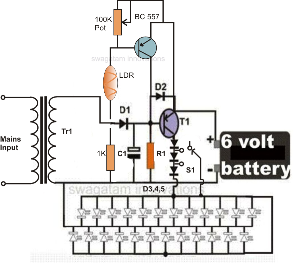
Automatic LED Emergency Light Circuit. This is the simple and cost effective automatic LED Emergency Light Circuit with light sensing. This system charges from main supply and gets activated when main supply is turned OFF. This emergency lamp will work for more than 8 hours (depending the battery capacity and the power consumed by the LEDs).
Automatic LED Emergency Light Circuit

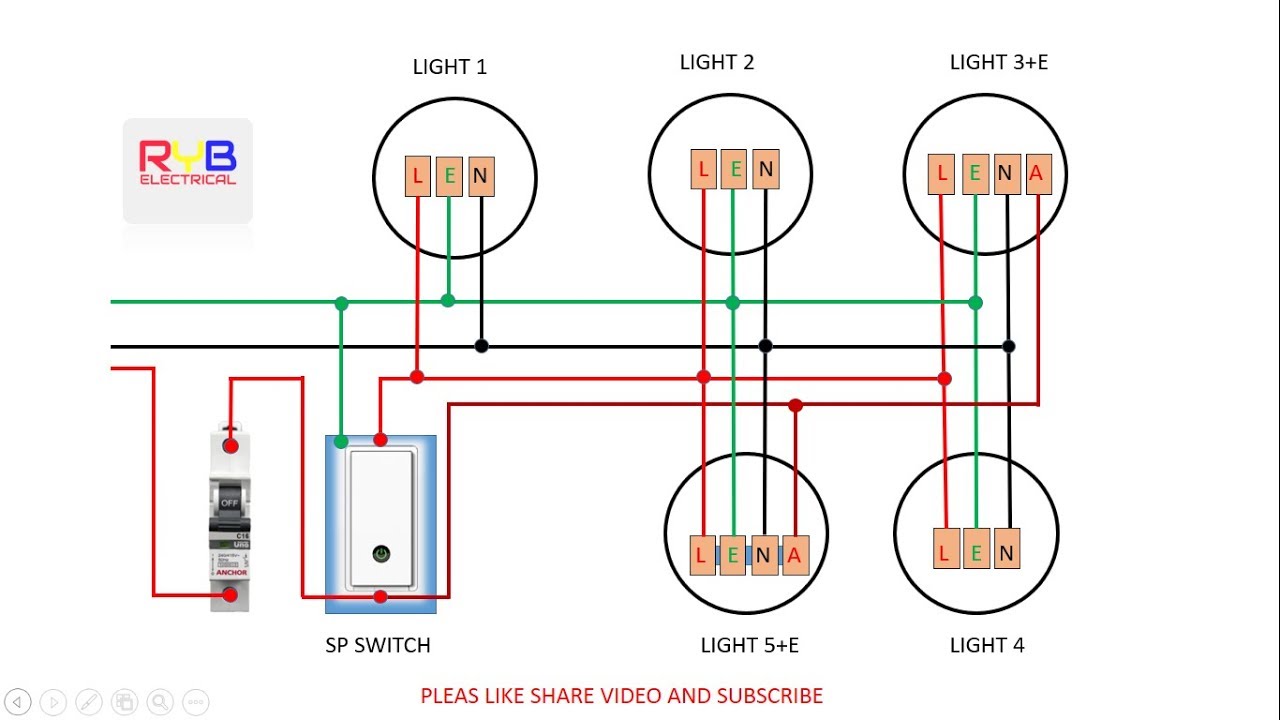
Terminal wiring diagram for a class I maintained emergency light fitting. Terminal wiring diagram for a class I non-maintained emergency light fitting. L SW is the normal mains supply. A normal light switch, or sensor, would usually be on this circuit to enable the end-user to have control over the light fitting in normal operating mode.
Circuit Diagram For Emergency Lighting System Circuit Diagram

Overall, having an Emergency Lighting Wiring Diagram is essential for any building. Not only does it provide a comprehensive overview of the lighting system, it also helps keep the system functioning properly. With the right wiring diagram, you can guarantee that your system is always ready to work when needed. Lbd 00418j.
Schematic Diagram Of Central Battery System Emergency Lighting Wiring

3.4.6 Connect the load circuits to the output terminals, fuses or MCB'S observe the correct polarity. 3.4.7 If the system is complete with integral sub-circuit monitors, fire alarm relay, terminals for connection of a remote alarm unit or terminals for remote indication of system fault via volt-free changeover contacts,
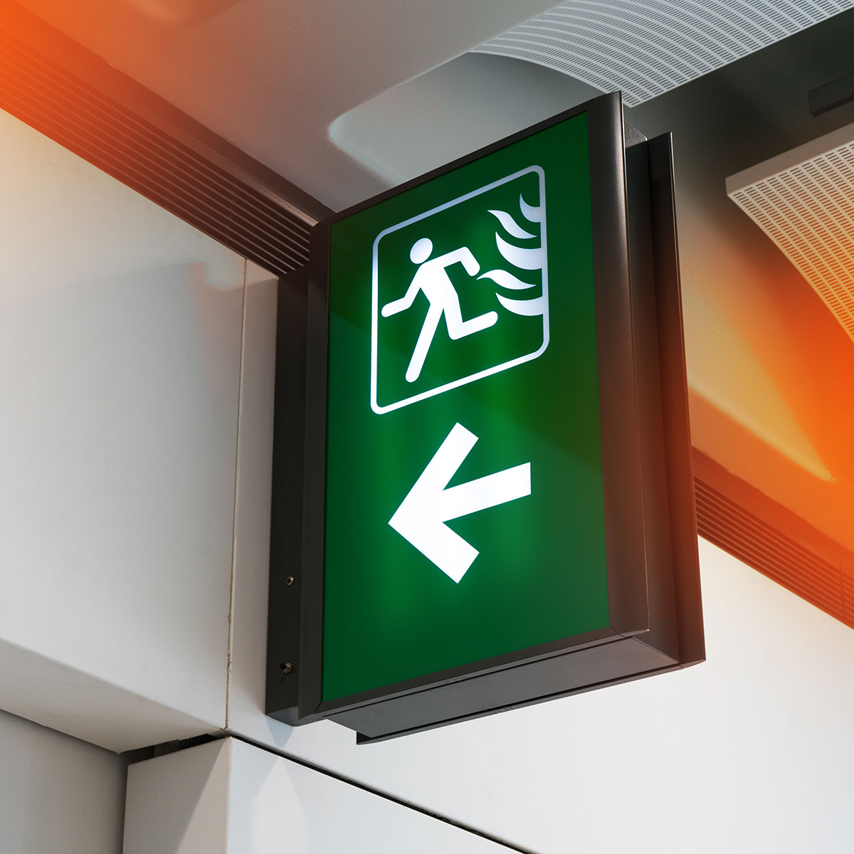
Emergency Lighting, Emergency Lighting Installers Vantage Systems
An emergency light schematic diagram is a visual representation of the electrical circuitry and components that are used in an emergency lighting system. It provides a clear and concise illustration of how the emergency light is wired and connected to a power source, battery, and various lighting fixtures.
Automaticemergencylightingcircuit »

BS 5266-1:2011 gives recommendations and guidance on the factors that need to be considered in the design of, and the installation and wiring of, electrical emergency escape lighting systems. This provides the lighting performance needed for safe movement of people in the event of the supply to normal lighting failing.
emergency light switch wiring diagram! YouTube
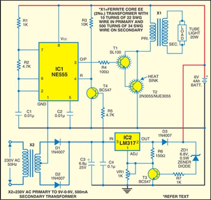
Wiring diagram for a ballast-free emergency fluorescent light system When it comes to emergency lighting systems, having a reliable and efficient wiring diagram is crucial. One common type of emergency lighting system is the ballast-free fluorescent light system, which provides backup lighting in case of power outages.
Emergency Lighting System — Projects Make Lighting system

Ul 1008 transfer switches for emergency systems only. (See sidebars for more information about the NEc and these Ul standards). Each of these standards focuses on a specific area of emergency or standby lighting and power, or describes a specific piece of equipment somewhere in the path of the emergency or standby lighting or power circuit.
Automatic Emergency Light Detailed Circuit Diagram Available
The basic process of how to wire emergency lights is as follows: Make the circuit safe for work to be carried out (as detailed above) Identify the voltage of the connection which will be made to the safety light fitting. Examine the unit connections. Connect the common wire and the right voltage wire for the connection voltage to the electrical.
Advance Emergency Light Circuit Best Engineering Projects

Minor revisions have been made due to the publication of the 2011 edition of theNational Electrical Code®. For some time, the proper control of emergency lighting circuits has been a topic of debate for manufacturers, systems integrators, and specifying electrical engineers. Much of the debate has centered on the proper application of the many.
Wiring Diagram For Emergency Lighting Wiring Digital and Schematic

The wiring diagram includes information on the placement and wiring of emergency light fixtures, emergency exit signs, and other components of the emergency lighting system. It often includes details on the size and type of wiring, circuit breakers, and other necessary electrical components. Following the wiring diagram accurately is crucial to.
Auto on/off Emergency lighting system

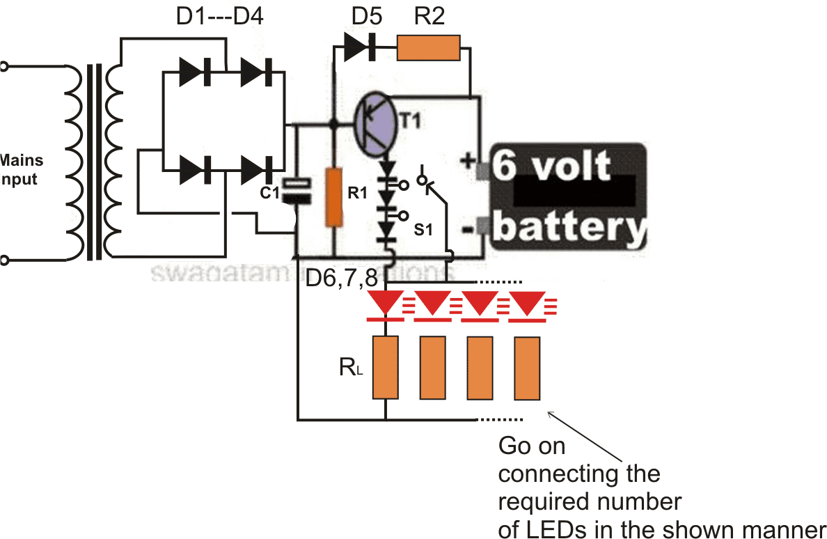
We can divide this LED emergency light circuit into two parts; first part is used to drop down the 220v AC voltage into 8v regulated DC, with the help of Transformer and bridge rectifier. And second part consists of Relay and rechargeable battery, which is used to lighten the LEDs during power failure. Components: Transformer- 9-0-9 500mA.
CONSTRUCTION OF AUTOMATIC EMERGENCY LIGHTING SYSTEM Afribary
The wiring diagram provides guidance on how to conduct these tests and outlines the procedures for recording and documenting the results. Compliance with these regulations is essential, and the wiring diagram plays a pivotal role in ensuring that the emergency lighting system meets the necessary standards. Any deviations from the requirements.
How To Wire Emergency Lighting Circuit Diagram Wiring Scan

This step-by-step guide will help you understand the process and ensure a successful installation. Step 1: Determine the circuit layout and load requirements. Start by identifying the area or areas that require emergency lighting. Calculate the total load required for the emergency lights in these areas.
10 Automatic Emergency Light Circuits Homemade Circuit Projects
9. Wiring Execution. Begin the physical wiring process based on the finalized and tested circuit diagram. Connect emergency lights, exit signs, batteries, switches, and other components according to the planned layout. 10. Insulation and Protection. Insulate wiring adequately to prevent electrical shorts or hazards.
Emergency Lighting Accell Electrical Ltd. Dublin

Emergency Lighting Mini Central Inverter System (Black) (Blue) (White) (Violet) Switched Command Signal (Not Suitable Dimming Circuits. Use Diagrams 3-6) (White) Earth Ground (Green) Input Wiring Neutral Line Line Output Wiring Switch Device (No Dimmers) Light Fixtures (LED, HID, Incandescent or Fluorescent) *Cap off unused wires Diagram #2
.